

 English
 русский
 Español
 Deutsch
 عربى
 Français
 Português
Don't hesitate to send a message
Single jacket, EPDM rubber liner Features • 100% high tenacity polyester jacket, high-grade EPDM rub...
Content
Friction loss is one of those quiet numbers that can make a good fireground plan work or leave a crew short of water. When you are calculating friction loss in fire hose, you are really asking how much pressure disappears as water pushes through the hose, fittings, and appliances before it reaches the nozzle. The formula is simple. The judgment around it is what takes experience.
Water does not glide through a fire hose without cost. As it moves, it rubs against the inner lining, changes direction at couplings and appliances, and loses energy to turbulence. That lost energy shows up as a drop in pressure. A pump operator has to make up for it at the panel so the nozzle still receives the pressure and flow the crew expects.
Several things drive the number:
The goal is not to memorize every number. It is to understand which variables matter and to use a consistent method your crew can repeat under pressure.
The standard fireground equation is usually written as FL = CQ²L. Each part has a specific job:
The most common mistake is plugging gallons per minute directly into the formula. If you use 150 instead of 1.5, the result will be wildly high. The same applies to length. A 200-foot line is 2, not 200. Keep the units consistent and the formula stays friendly.
The coefficient is not a permanent property of a hose size alone. It is a planning value. New hose, old hose, kinked hose, and different lining materials can all produce different results. Manufacturer test data and your own field checks are the best sources for the coefficient you adopt.
| Hose size | Typical C | Common use |
|---|---|---|
| 1¾ inch | 15.5 | Attack line |
| 2½ inch | 2 | Attack or supply |
| 3 inch | 0.8 | Supply line |
| 4 inch | 0.2 | Supply line |
| 5 inch | 0.08 | Large supply line |
Suppose you are running 200 feet of 1¾-inch attack hose at 150 gpm. Using a typical coefficient of 15.5, the calculation looks like this:
That is about 70 psi lost in the hose. If the nozzle needs 100 psi, the pump pressure has to be roughly 170 psi before you add anything for appliances or elevation. On a flat lot with no extra fittings, that simple total is often close enough for a quick check. Add a wye, a standpipe, or a climb, and the target pump pressure moves.
If you are comparing hose options for that kind of attack line, a single-jacket EPDM rubber liner attack hose is one construction to review. It is the kind of line many departments use when they want a balance of durability and handling.
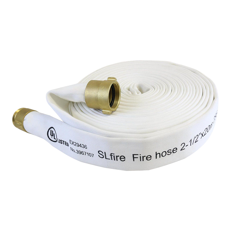 Single-Jacket EPDM Rubber Liner Attack HoseSingle-jacket attack hose with EPDM liner and high-tenacity polyester jacket, suited to firefighting water delivery and comparison for durability and handling.View Product →
The example also shows why flow matters so much. If that same line were flowing 200 gpm, Q becomes 2, Q² becomes 4, and friction loss doubles to about 124 psi. The hose did not change. The demand did.
Not every pump operator will pull out a calculator at 2 a.m. Many departments use a hand method, a pump chart, or a slide rule-style reference for common hose sizes. These tools are useful because they turn the formula into a repeatable field decision. They are not shortcuts around understanding. They are memory aids built on the same math.
A hand method for 1¾-inch hose gives a fast estimate without writing anything down. The key is to use the method your department has adopted and to know the assumptions behind it. If the chart assumes 100 psi nozzle pressure and a certain hose coefficient, do not expect it to match a different nozzle or a different hose construction.
Field checks are just as important:
For a deeper look at how hose holds pressure during operations, this explanation of how fire hoses maintain their pressure during firefighting operations is a useful companion to the math.
Two hoses can share the same diameter and still behave differently. The inner lining affects how smoothly water moves. A rubber liner, a TPU liner, and a PVC liner each have their own feel and flow characteristics. The jacket protects the hose and influences how well it resists abrasion, pressure, and kinking. Age matters too. A hose that has been folded in the same place for years may develop soft spots or memory that change its performance.
Couplings and nozzles also leave a fingerprint on the total. A restrictive coupling, a damaged gasket, or an appliance with a narrow waterway can add loss that the basic hose formula does not see. That is why experienced operators treat the formula as a starting point and then look at the whole layout. The pump does not know hose from appliance. It only knows that pressure is disappearing somewhere.
For larger supply lines, a double-jacket EPDM rubber liner supply hose is a common starting point when you need a balance of durability and flexibility. It is built for the kind of work where water has to travel a long way before it reaches the fire.
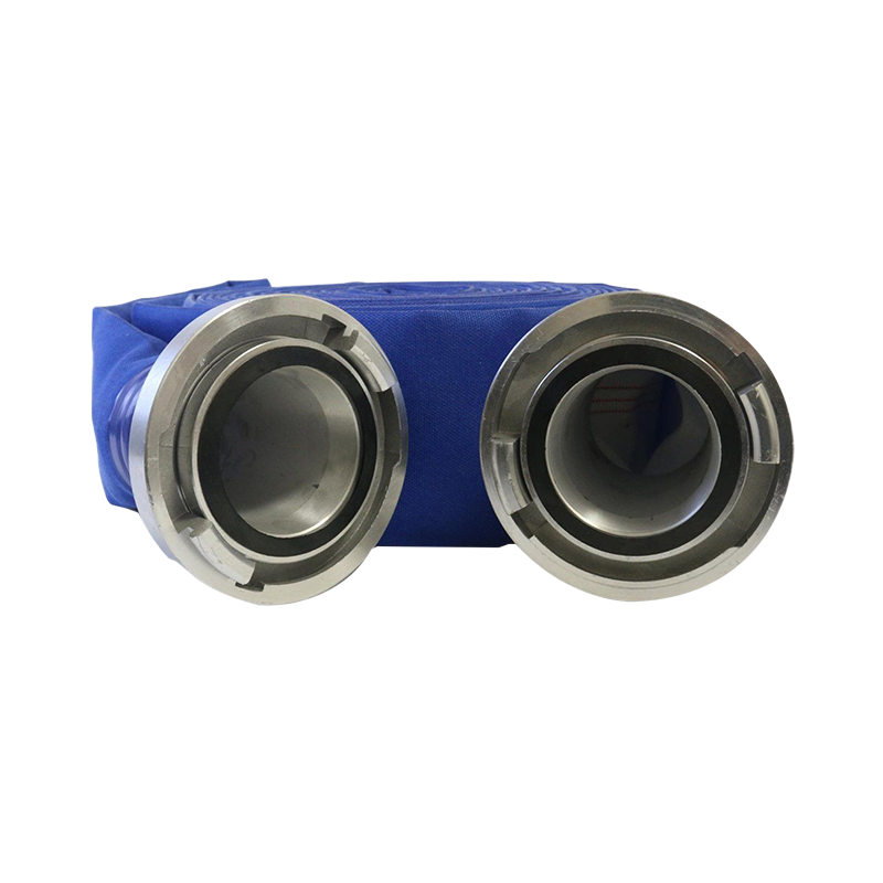 Double-Jacket EPDM Rubber Liner Supply HoseDouble-jacket supply hose with EPDM liner and high-tenacity polyester jacket, built for large-volume water movement with low friction loss and abrasion resistance.View Product →
This is also why hose records matter. If you track the age, testing history, and field performance of each hose, you can refine your coefficients over time. A pump chart based on real hose is better than a pump chart based on a catalog number.
Most friction loss errors are not math errors. They are assumption errors. Here are the ones I see most often:
None of these mistakes is unusual. The fix is a simple routine: write down the flow, length, hose type, appliance allowance, and elevation before you set the pump pressure. A consistent worksheet beats a mental guess, especially when multiple lines are running.
A good pump chart is short enough to use and specific enough to trust. You do not need a complicated spreadsheet to start. Begin with the hose sizes and nozzles your department actually runs, then build the chart around common flows.
Test the chart against actual pump operations when you can. If the chart says 170 psi and the nozzle is not performing, find out why. Maybe the flow is higher than expected. Maybe an appliance is adding loss. Maybe the hose is older than the coefficient assumes. The chart should start a conversation, not end one.
Calculating friction loss in fire hose is not about chasing perfect numbers. It is about giving the nozzle crew what they need with a pressure that makes sense. The formula FL = CQ²L is simple enough to use on the back of a glove, but it only works when you respect the units, the hose, and the conditions in front of you.
From our side of the hose bench, the best calculations are the ones that get checked in the field. Know your hose. Know your flows. Keep your pump chart honest. Then adjust when the fireground tells you something different.
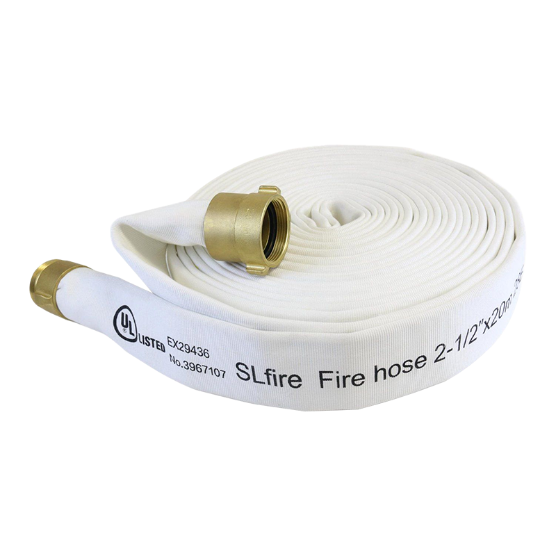
Single jacket, EPDM rubber liner Features • 100% high tenacity polyester jacket, high-grade EPDM rub...
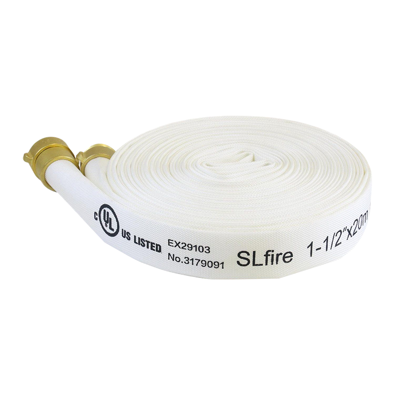
Single jacket, TPU liner •High-tenacity polyester yarn, circular woven in twill weave/plain weave,T ...
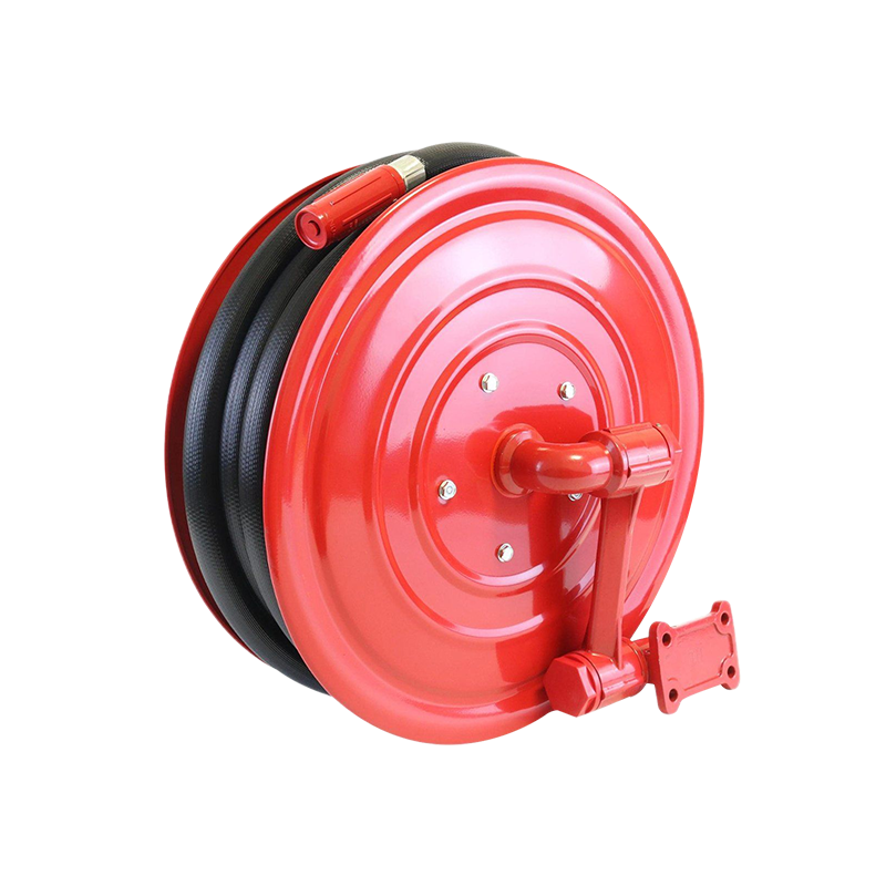
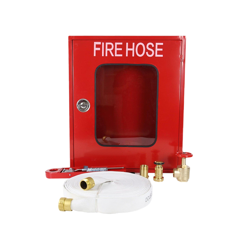
Fire cabinets are designed to accommodate fire hose,valve and other firefighting equipment. Type 201...
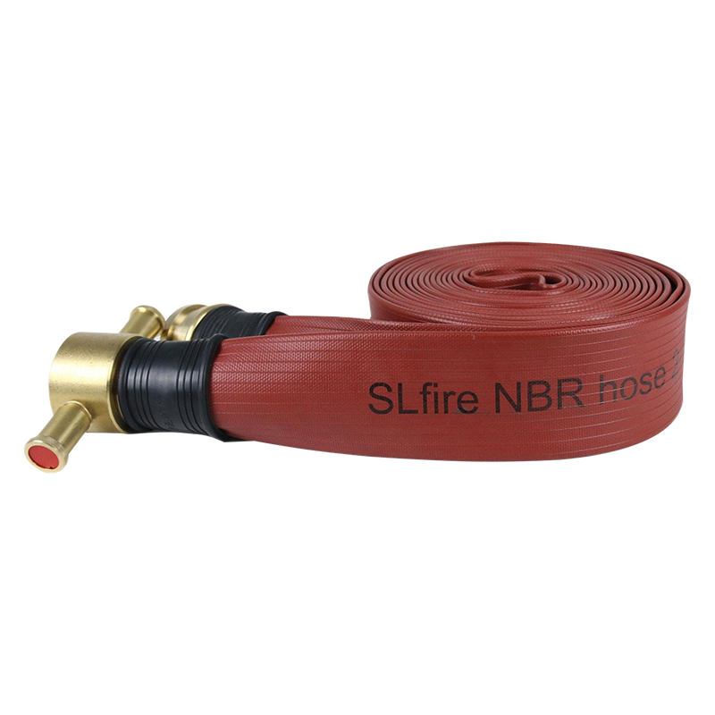
Nitrile covered hose •Nitrile/TPR blend as cover and lining, with 100% high-tenacity polyester yarn ...
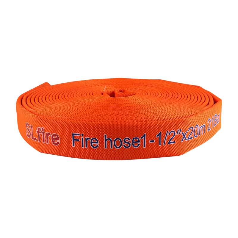
Single jacket, TPU liner •High-tenacity polyester yarn, circular woven in twill weave, TPU lining, f...
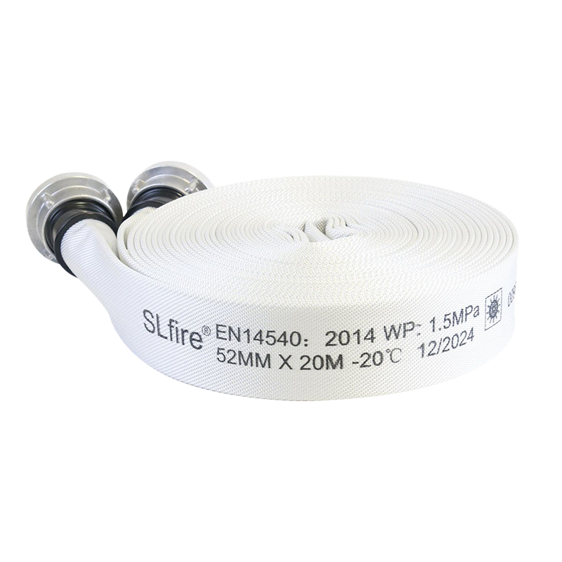
Marine hose Single jacket, PVC liner •100% high tenacity polyester yarn, circular woven in twill wea...
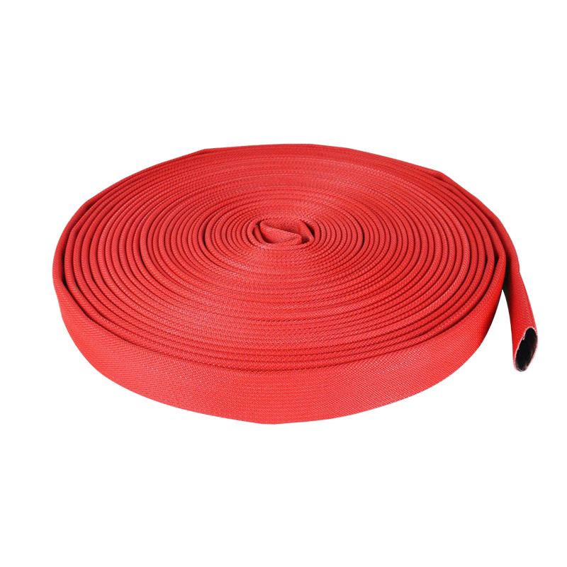
Marine hose Single jacket, PVC liner, PU coated •100% high tenacity polyester yarn,c ircular woven i...
 Call Us
+86 159-5116-9511
Need Support
Head Office
No.58, Kechuang Road, Sixiang Street Medicine Gaoxin District Taizhou City, Jiangsu Province

Friction loss is one of those quiet numbers that can make a good fireground plan work or leave a crew short of water. When you are calculating friction loss in fire hose, you are really asking how mu...
Copyright © Taizhou Shenlong Fire Science and Technology Co., Ltd. All Rights Reserved.
 Fire Hose Manufacturers, Fire Hydrant Hose Factory